HKUST Robotics Team - The 14th Robot Design Contest 2022
Group 5 Fibotics - TR (Task Robot)
Oct - Dec 2022
Technologies: STM32, Pneumatic Control, CAN Bus, TOF Sensors, Bluetooth (HC-05), MIT App Inventor, Embedded C, Omniwheel Kinematics, RoboMaster M3508 Motors, C620 ESCs
🎯 Game Task Overview
The Task Robot (TR)
- is a manual/semi-automatic robot.
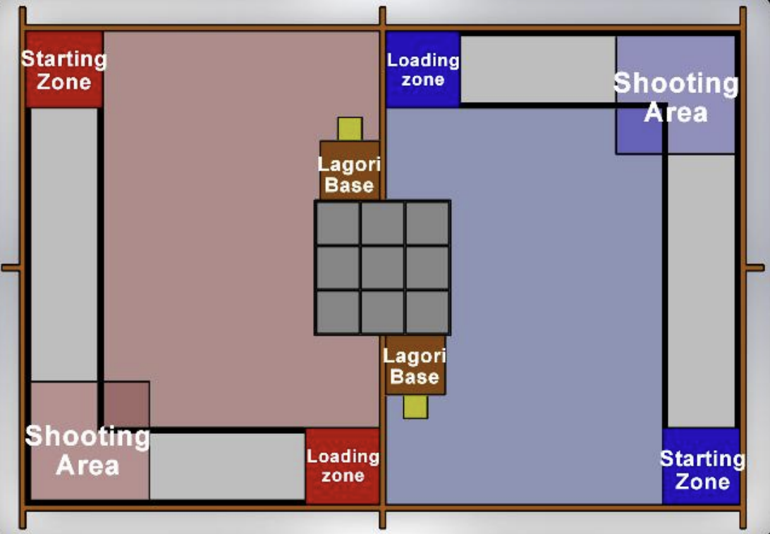
- starts from the red/blue Starting Zone.
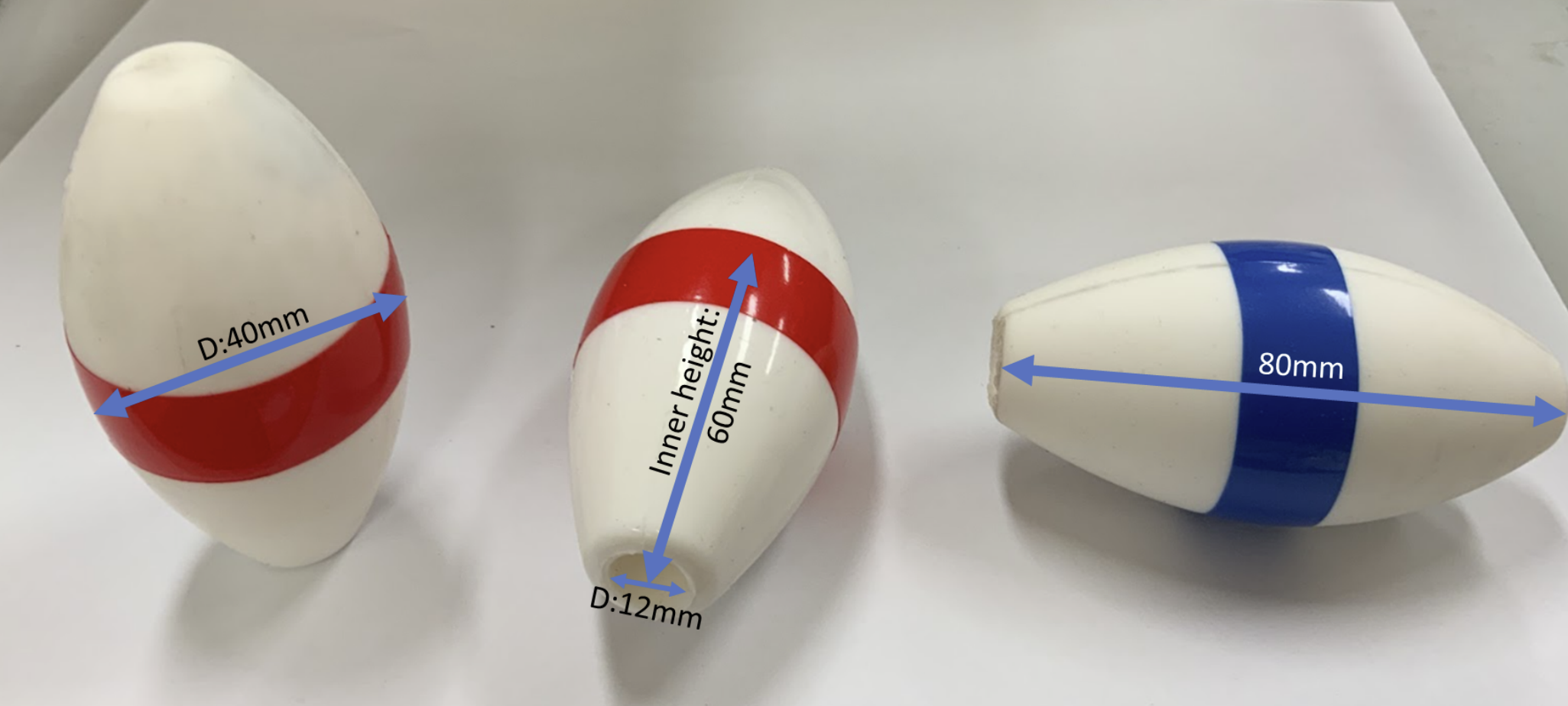
- load 1 Piece from the Loading Zone.
- shoot Pieces from the Shooting Area into the Tic-Tac-Toe boxes to form a line of three.
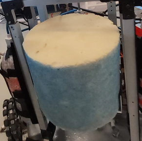
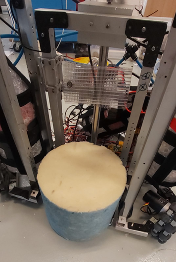
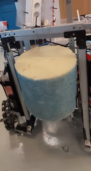
- Optionally perform the Lagori task (lifting Lagori (a cylindrical sponge) onto a base) to “unlock” the ability to place Pieces directly into the Tic-Tac-Toe boxes without shooting.
- Automatically travels along the Auto-ShortCut (the L-shape path) to load up to 3 Pieces from the Loading Zone at the same time.
Overview
The Task Robot (TR) was responsible for interacting with the Tic-Tac-Toe boxes and handling the Lagori task. I contributed to the software development, including the Bluetooth command system, the move coordinate system, and low-level motor control.
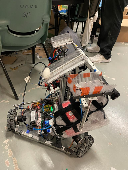
Mechanisms
Dropping Mechanism
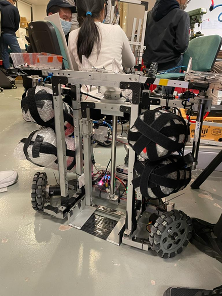
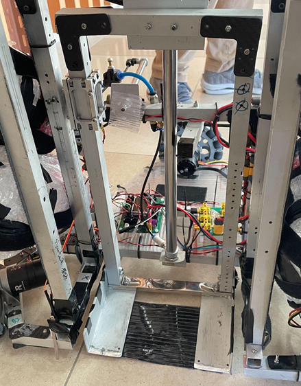
The TR featured three separate rails of different lengths to hold and drop pieces into the tic-tac-toe boxes. The rails were connected by hinges and initially slanted backward to prevent pieces from rolling out. Three pneumatic cylinders pushed the rails upward, slanting them forward so that pieces rolled down along the rail into the correct box.
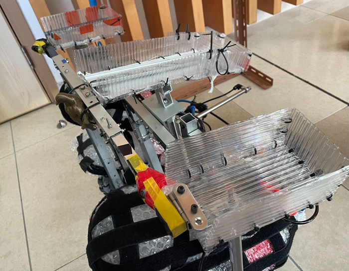
Loading Mechanism
A passive loading system was installed at the loading zone. When the TR arrived, it hit the handle of the loading racks, releasing pieces onto the TR's built-in rack per rail. The rails were set at -45° to hold the pieces firmly.
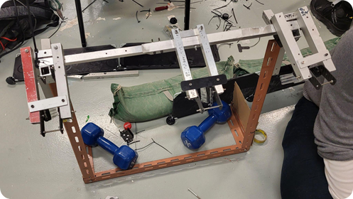
Lagori Task Solution
A sweeper-lifter was attached to the back of the TR, with an initially extended pneumatic cylinder. The sweeper swept the Lagori into the lifter. When the cylinder retracted, the lifter rose above the Lagori base, and the TR moved forward to drop the Lagori onto the base. A horizontal cylinder at the back provided an extra push to ensure firm placement.
Software & Control
Basic Motor & Omniwheel Wheelbase Control
The TR was powered by RoboMaster M3508 motors driven by C620 ESCs over a CAN bus. I implemented a PID controller for precise velocity control. The M3508's built-in hall-effect sensors provided feedback for close-loop speed regulation, while the C620 handled the high-current commutation.
The robot used an omniwheel configuration, allowing it to move in any direction without changing its orientation. I developed the wheelbase kinematics library that translates desired chassis velocities (vx, vy, ω) into individual wheel speeds. This enabled complex manoeuvres like rotating while translating - essential for precise alignment on the track.
Basic Bluetooth Command System (MIT App Inventor)
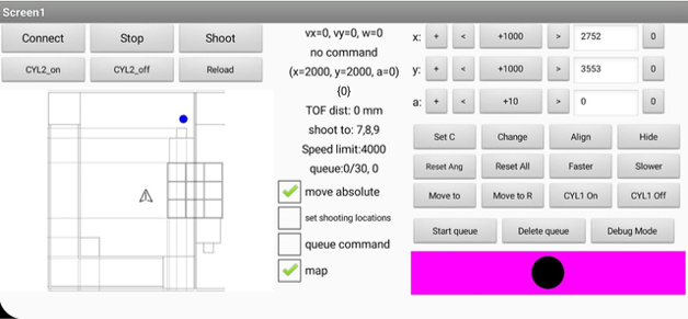
I developed a custom Android application using MIT App Inventor to remotely control the TR via an HC-05 Bluetooth module connected to the STM32 mainboard through UART.
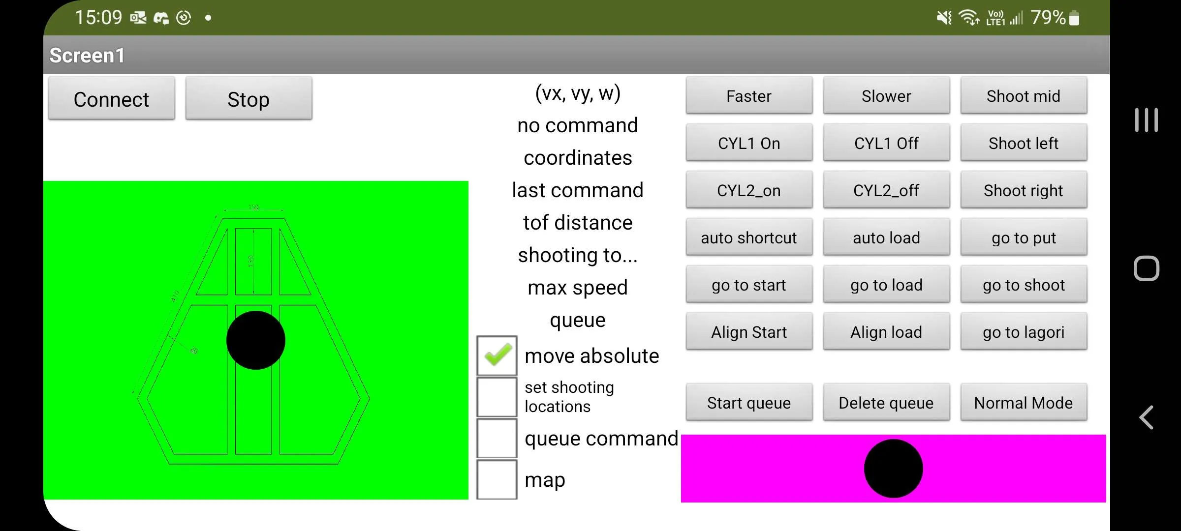
The app features
- a 2D joystick on the left for lateral movement
- a 1D joystick on the right for rotational movement
- a Faster and Slower button to change the wheelbase's max speed
- a "Move Absolute" checkbox to determine whether the movement is referenced to the wheelbase frame or the gamefield frame
- some buttons on the right to control different mechanisms on the robot
- some buttons on the right to activate auto paths
- real-time display of the robot's velocities and sensors feedback
where
- x, y is the lateral wheelbase movement in x, y diretcion,
- rotation_angle is the angle of the rotation joystick,
- command is the instruction for the robot to execute (e.g., shoot left, move to loading zone, etc.)
The STM32 firmware parses incoming commands and executes them. The Bluetooth system proved reliable during competition and greatly simplified driver operations.
Advanced Move Coordinate System
Using motor speed feedback from the CAN bus, the TR's position (x, y, angle) was calculated using some
self derived inverse kinematics equations. This enabled precise automatic movement by simply controlling
the robot to move to (x: 1000mm, y: 0mm, angle: 90 degree).
As the (x, y, angle) is calculated using the motor speed feedback from the omniwheels, it is just
relative localization. So, we have to align to the walls of some key points and measures the horizontal
distance using a TOF sensor, to calibrate our robot's position relative to the gamefield. This allows
the robot to move to different key points on the gamefield with high precision. The coordinates of the
gamefield is defined like this:
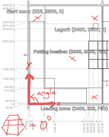
The (x, y, angle) coordinates is transmitted back from STM32 to the MIT App. This allows the app to show the robot's position of the gamefield in real time (the arrow). I have created this Advanced Move Coordinate System for the driver to move the robot to any desired location by simply clicking the same spot on a map (the blue dot).
Awards & Recognition
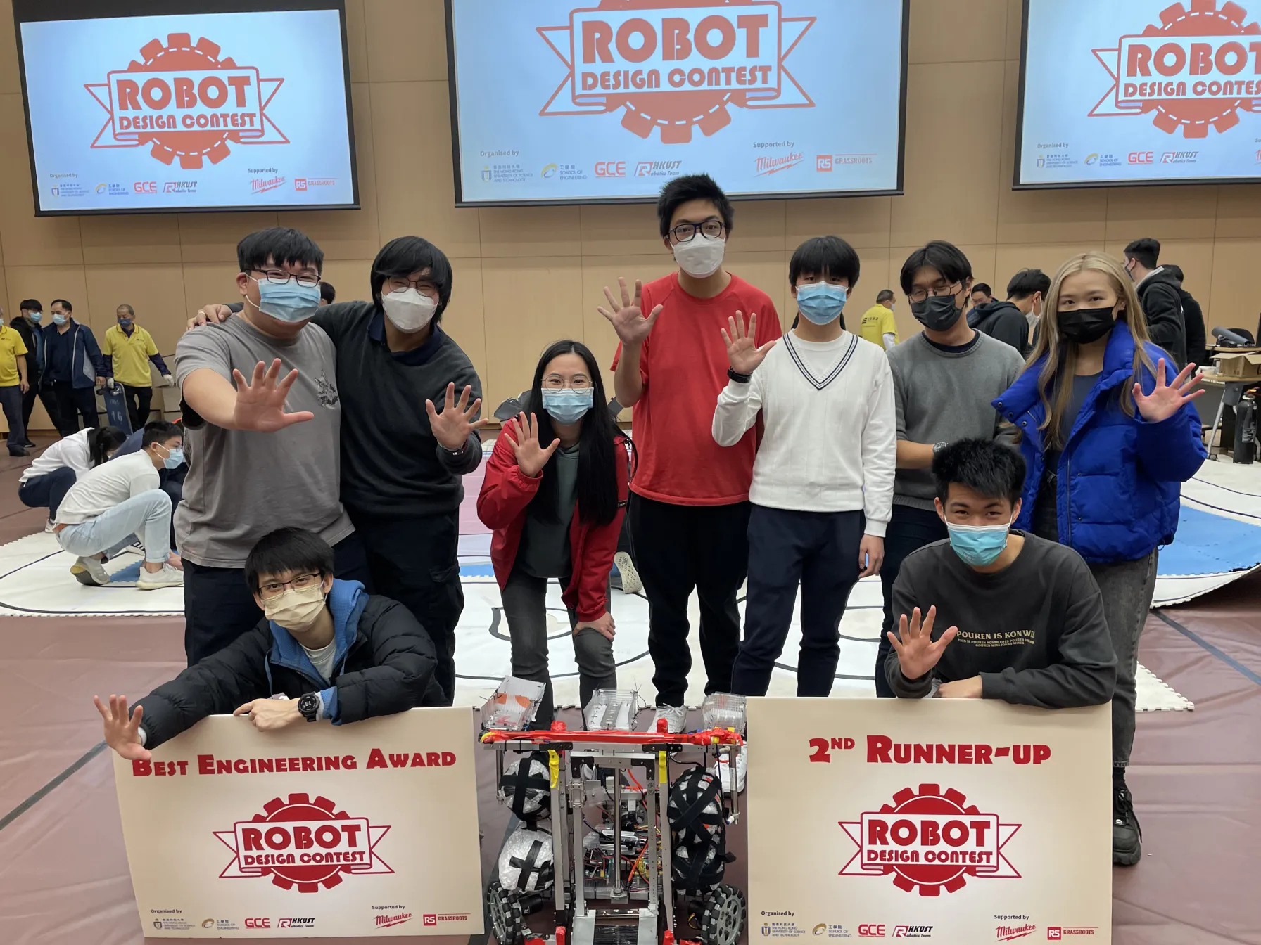
- 🏆 HKUST Robotics Team - The 14th Robot Design Contest 2022 - 2nd Runner Up
- 🏅 HKUST Robotics Team - The 14th Robot Design Contest 2022 - Best Engineering Award